Floor Chart
The reconstruction pipeline estimates camera and subject geometry in an arbitrary coordinate system, usually with the origin attached to one of the solved cameras. It also reconstructs at an arbitrary scale. A floor chart provides known geometry in the capture volume so the final model can be aligned, oriented, and scaled in metric units.
The chart is based on the ArUco library that ships as part of OpenCV.
Board Generation
example_aruco_create_board
The following parameters control the creation of the board:
- d - dictionary: DICT_4X4_50=0, DICT_4X4_100=1, etc…
- w - Number of squares in X direction
- h - Number of squares in Y direction
- l - Marker side length (in pixels)
- s - Separation between two consecutive markers in the grid (in pixels)
- m - Margins size (in pixels)
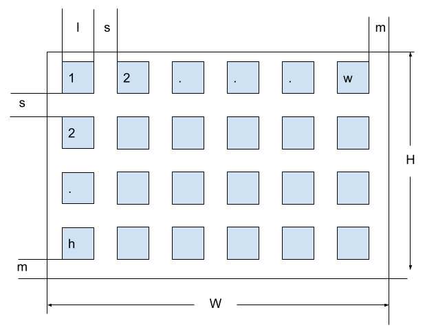
Figure 1: ArUco board layout.
Given the parameters that control the drawing of the board and known structure, it is possible to formulate the width and height of the board in pixels as follows:
W=2m+wl+(w-1)s
H=2m+hl+(h-1)s
Making $s$ proportional to the size $l$ using variable $x$
W=2m+wl+(w-1)xl
H=2m+hl+(h-1)xl
Setting $W$ and $H$ to the size of A0 in pixels at 300 dpi removing the margin
W_p = 1.189/0.0254*300 = 14043
H_p = 0.841/0.0254*300 = 9933
14043=wl+(w-1)xl
9933=hl+(h-1)xl
The computed parameters can therefore be used to generate an A0 sized ArUco board at 300 DPI suitable for high-quality printing.
./example_aruco_create_board -d=1 -w=9 -h=7 -m=0 -l=900 -s=585 floor-chart_7x5_a0.png
The generated image was then edited to remove the central portion of markers and replace it with footprints and arrows representing the X-Z plane. This gives the subject a clear standing position while preserving known fiducial markers around the capture area.
The image below shows the final floor chart after editing.
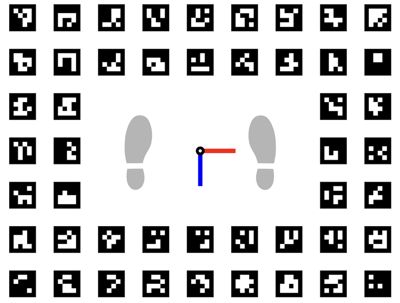
Figure 2: Final floor chart.